


CBCT is quickly becoming the standard of care for dental radiographs. As more dentists experience the radiographic information that CBCT offers, they are realizing that doing certain procedures without CBCT increases the risk of failure. If you are new to CBCT or are considering purchasing a CBCT unit, the following information may be helpful in preparing you for what you should learn at a minimum.
1) What you are looking at:
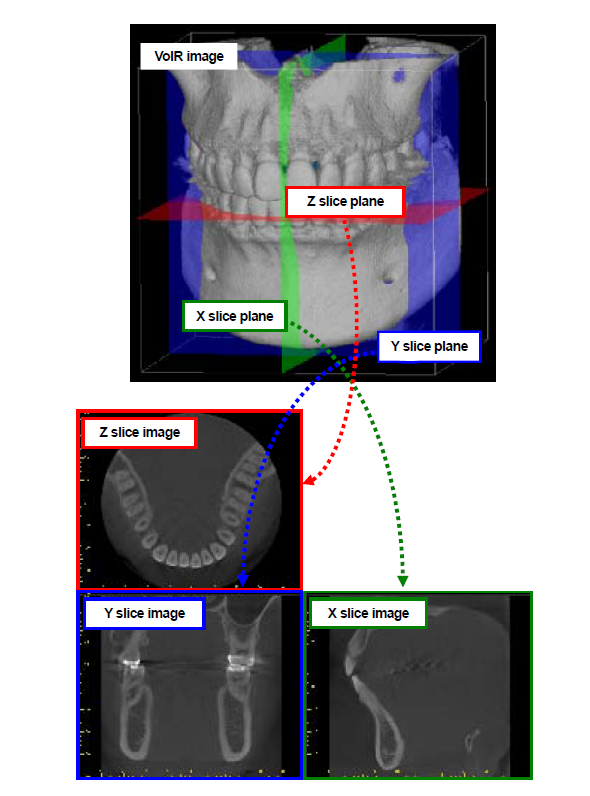
3 views and a volume rendered view—VoIR-- which is a compiled 3D model of whatever was captured. In the image below, both the upper and lower mandibles were captured.
Axial View – also referred to as the Z axis. This is the view from head to toe. In most software, moving the line corresponding to the axis allows for moving through the slices in that plane. Notice below that each slice is represented in the VoIR and is then represented in the corresponding axial, coronal, and sagital views.
Coronal View – also referred to as the Y axis.
Sagittal View – also referred to as the X axis. This is the view from the side of the skull.
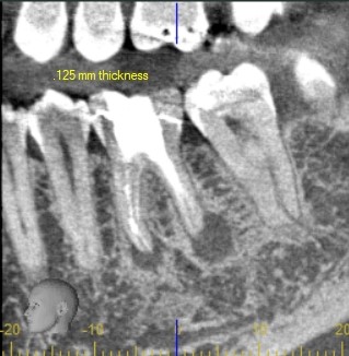
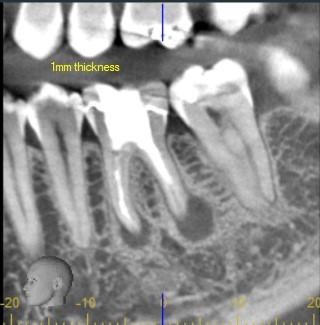
2) Slices along the X,Y, and Z axes, and the difference between slice thickness and slice interval.
When you vary thickness or interval what change does it make to the image quality? What settings are best for what procedures? In general, a 1mm slice thickness and 1mm interval are the best for implant planning. If you are evaluating an endo case, a ½ mm interval may be better for detecting fractures. In general, when you drop to thinner slices the resulting image appears grainy because there is less information. The following are the same images at different slice thicknesses. Notice at the smallest slice thickness of .125 the image appears grainy, and that the image smooths out as slice thickness increases and there is more composite information.
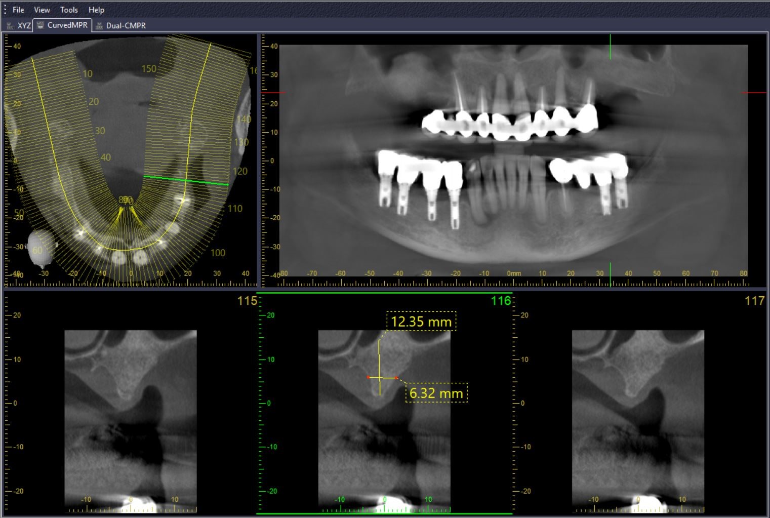
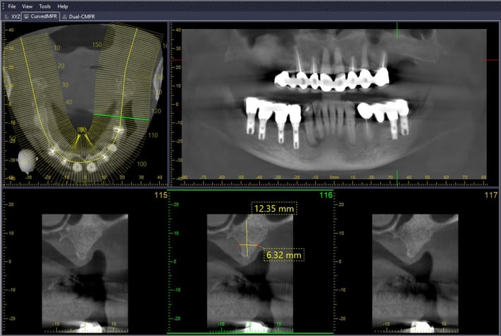
3) How to draw an MPR line (multi-planar reconstruction line) and view slices along that line.
This is one of the most commonly used tools for endo and implant planning. With this tool, a line can be drawn on the axial view. Slices along the line are created for evaluating bone quality/ quantity and other anatomical landmarks such as the mental foramen and sinus. In the following image, MPR measurements are placed on a slice where an implant is planned.
4) How to accurately measure using the measurement tools.
A good understanding of how to make accurate measurements in your CBCT software will allow you to plan cases with a much greater degree of accuracy.
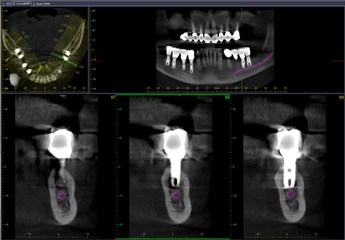
5) How to identify and mark the mental foramen.
Most software makes this process pretty easy. The marked nerve appears in all views for correct implant planning. The following image demonstrates the ability to mark the nerve in every view to easily allow avoidance of the nerve when implant planning.
6) How to select and place an implant.
Most CBCT software has an implant library with properly sized implants that can be dropped into the scan to determine ideal placement. If your implant manufacturer is not in your chosen software, you can still create a custom implant that will be the correct size. Below is an example of placing an implant in BlueSky Bio planning software.

7) How to evaluate bone quality and quantity with density measuring tools.
Apart from grayscale variances that can allow the clinician to see bone levels and access quality, some software allows for measuring density differences from one point to another. These tools are beneficial for getting relative density measurements in the software.
8) How to screenshot views for reports or referring Drs.
It is important to know how to easily screenshot important images to create a report for the lab or a referring clinician. If your software is weak in its reporting ability, the Windows snipping tool and Microsoft Word allow for the creation of report style templates.
9) How to export in DICOM to open in 3rd party planning software.
Exporting in DICOM is a feature that all CBCT software should have. This allows the clinician to share the files with a colleague who may have a different DICOM planning software. It also allows for the import into more sophisticated software that gives the option of combining STL (such as acquired from an intraoral scanner) and DICOM from a CBCT to create a surgical guide as illustrated in the image below.

10) How to send the DICOM to a third party via HIPPA compliant sharing software.
It is important that you know how to send the file to a third party and abide by HIPPA regulations. You must have a business associates agreement in place as well as a password protected file. Services such as sendthedoc.com and biobigbox.com insure that all the HIPPA criteria are met.
High tech dentistry is changing treatment planning and treatment outcomes for the better. CBCT is a fascinating technology that will someday be standard of care in dentistry. If you are planning on getting into CBCT, knowing the preceding information about your system will make the transition smoother and more rewarding. For more information, feel free to contact us by email at info@dentalti.com or by phone at 1.800.672.5733.
Leave Comment